Fronius
Installation and configuration
Interface: LAN
Supported series
Fronius PrimoFronius
SymoFronius
Primo GEN24 plusFronius
Symo GEN24 plus
Brief instructions
Integration of the inverter (WR):
- Integrate the WR into the local network.
- Go (via the browser) to the user interface of the WR.
Settings:
| category | setting | |
|---|---|---|
| Technician Wizard | dynamic power reduction > power limit | no limit |
| Solarweb Wizard | Network Setup > LAN Settings | automatic |
| Settings | Modbus > Data output via Modbus | tcp |
| Modbus > Control via Modbus | active | |
| If necessary, activate night mode of the data interface | ||
- It may be necessary to restart the WR and the router.
Configuration Fronius Primo or Symo WR
- Connect your laptop to the local network (via LAN cable or WLAN).
- Open (via browser) the Fronius commissioning wizard: http://datamanager
- Select Technician Wizard
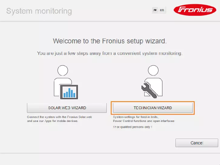
- Follow the installation steps and fill in the forms of the submenus.
- In the Dynamic Power submenu, activate the No Limit radio button
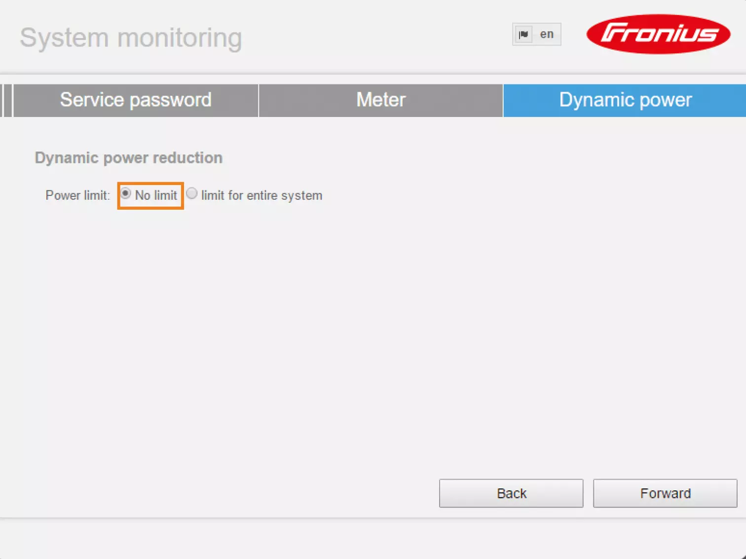
- Click Next and switch to the SOLAR WEB ASSISTANT.
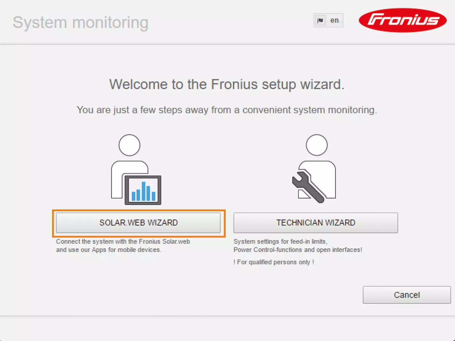
- Activate the Radio button dynamically.
- Click Connect.
- Follow the installation steps and fill in the forms of the submenus. Click Save.
- Click the Settings button.
- Select the MODBUS menu item.
- Under Data output via Modbus, select the tcp radio button.
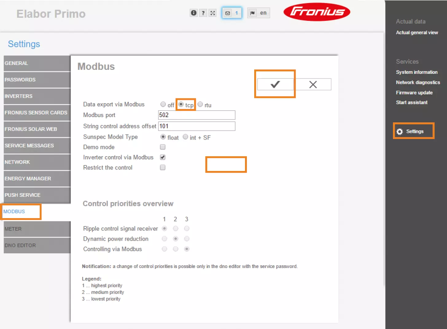
- Click Save
Configuration Primo GEN24 plus / Symo GEN24 plus
Fronius inverters of the Primo GEN24 Plus and Symo GEN24 Plus series are not found and installed by autodiscovery in Manager SmartSetup. The device search must be performed by entering the IP address of the WR. If the IP address changes during operation, the connection between the inverter and the manager is lost.
We therefore recommend assigning a static IP address to the WR via its network settings.
- Go (via a browser) to the user interface of the WR.
- Click on the Communication menu item.
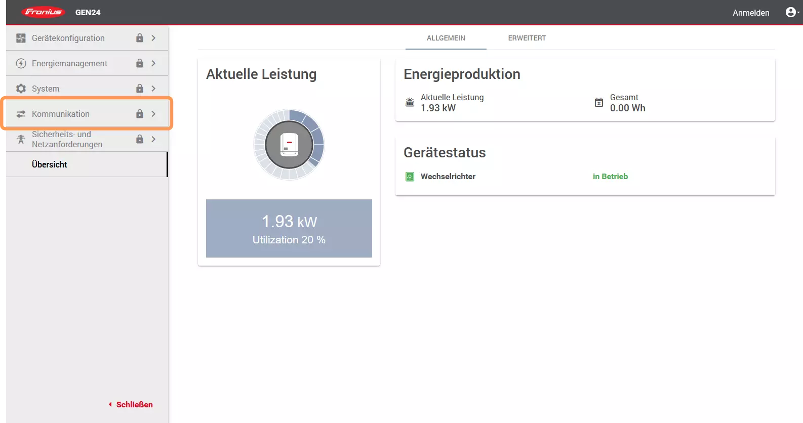
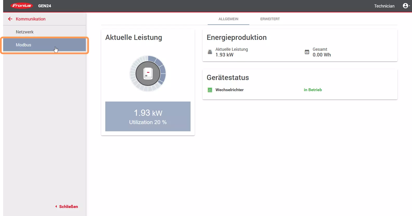
- Enter the access data.
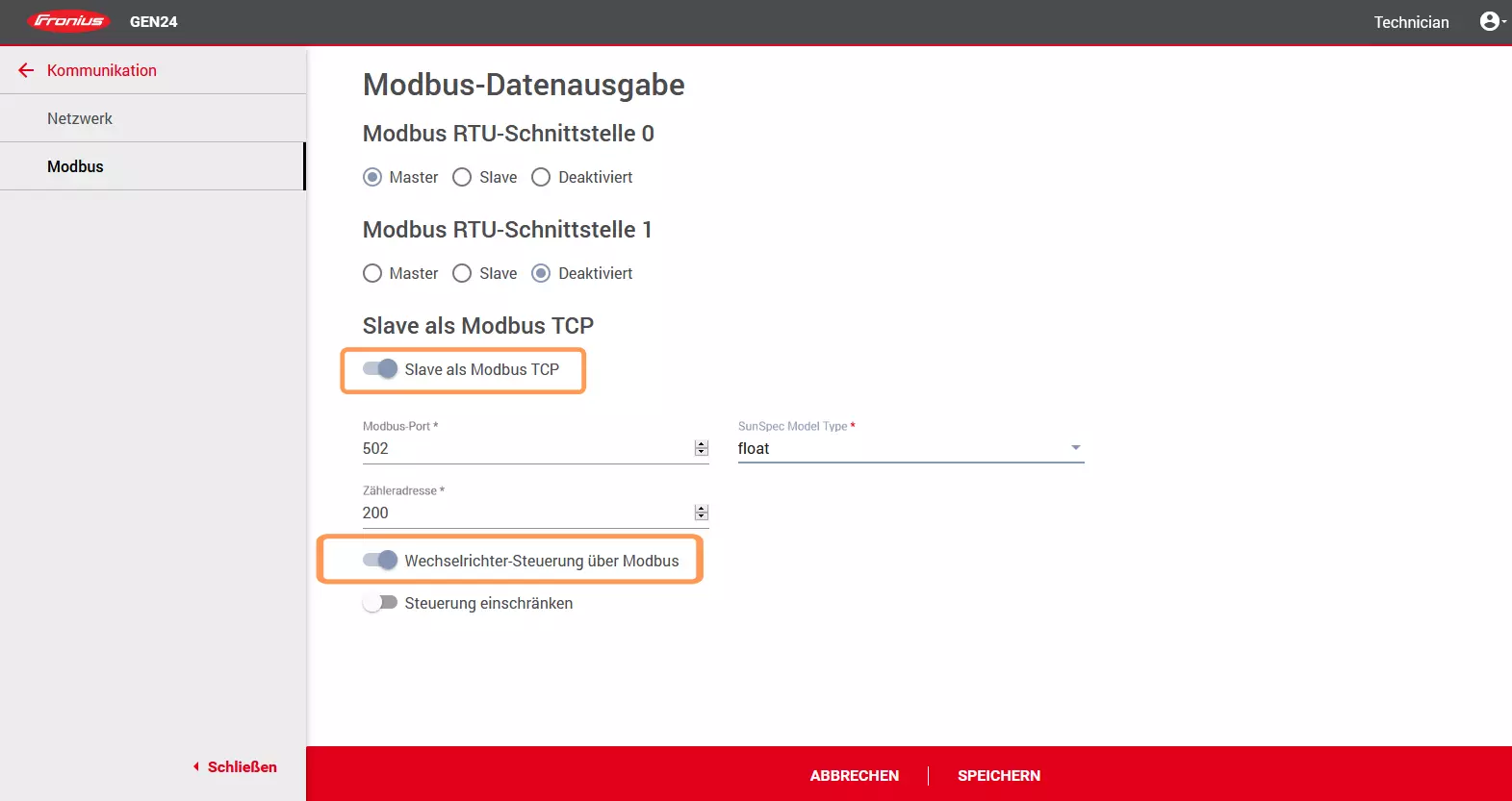
- Click on the Modbus menu item.
- Activate the option Slave as Modbus TCP and inverter control via Modbus.
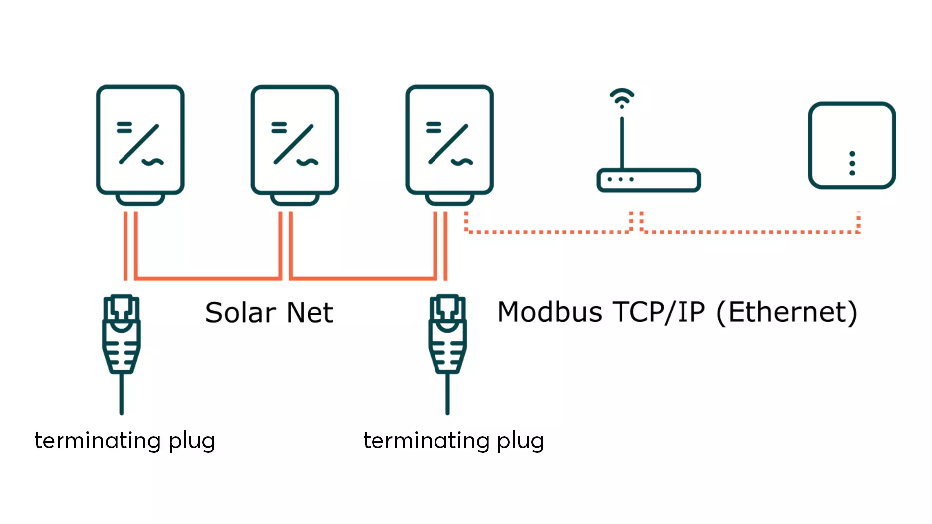
Connecting several Fronius inverters with Fronius Solar Net
Fronius Solar Net is a communication protocol between Fronius inverters. It can be used to connect up to 100 Fronius inverters with each other. Only one WR (master) needs to be integrated into the local data network.
- Define the WR that is integrated into the local network via Ethernet as the master in the WR settings.
- Define all other inverters connected via Fronius Solar Net as slaves.
- Assign each inverter its own DATCOM address (1 ... 100).
- For communication between the inverters, you must set the terminating plugs on the inverters at the start and end of the ring.
For more information on setting up a Fronius Solar Net, please refer to the Fronius help pages.
Activate night mode of the data interface
You must activate the night mode so that the Fronius data manager (communication center in the Fronius WR) can also be installed during the night or when there is insufficient DC voltage. Otherwise, the data interface will go into standby mode.
- Open the menu item SETUP on the display of the WR.
- Select the submenu Display settings.
- Select the Night mode entry.
- Select the ON setting.
- Press Enter.
After you have successfully commissioned the Fronius Data Manager, you can deactivate the night mode again.
Setup in SmartSetup
The Primo and Symo models are found and installed by the automatic device search, provided they are accessible on the local network.
The automatic device search and installation can take up to 5 minutes.
Correctly installed devices can be recognized by the message: Device is installed. in the device list. Furthermore, the list shows the current creation data.